After removing the top and bottom covers and tipping the 5370A on its side to facilitate probing, I discovered that:
1) The START and STOP input amplifiers amplifiers were behaving normally and produced START and STOP signals.
2) The inputs and outputs of the arming assembly (A22) START flipflop (A22U17) were behaving as expected with logic levels of 0V and -0.6V for the 2 logic states.
3) The inputs and outputs of the arming assembly (A22) STOP flipflop (A22U21) were abnormal with logic levels of -0.6V and -1.2V for the 2 input logic states and the Q output was stuck at 0V.Since the outputs of the EECL logic involved are actually open collector switched current(12mA) sources with external 50 ohm load resistors connected to ground, it appeared that the inputs of U17 were sinking excessive current. Since the inputs are actually npn emitter followers the input current should be relatively small (< 1mA).
Fortunately there are external series resistors between the load resistors terminating the transmission lines (microstrip or coax) connecting the EECL driver chip outputs and the inputs of the START and STOP flipflops. When these resistors were disconnected from the STOP flipflop clock and data input pins the logic levels across the 50 ohm load resistors were restored to the expected 0V and -0.6V levels.
Since all the input pins (including the undocumented ones) of the STOP flipflop exhibited this behaviour it was likely that there was a common cause. The most likely cause (since a DVM showed that there was at least one operational pn junction between each chip input and the -5.2V supply pin) was that the internal IC ground bond wire was open circuit.
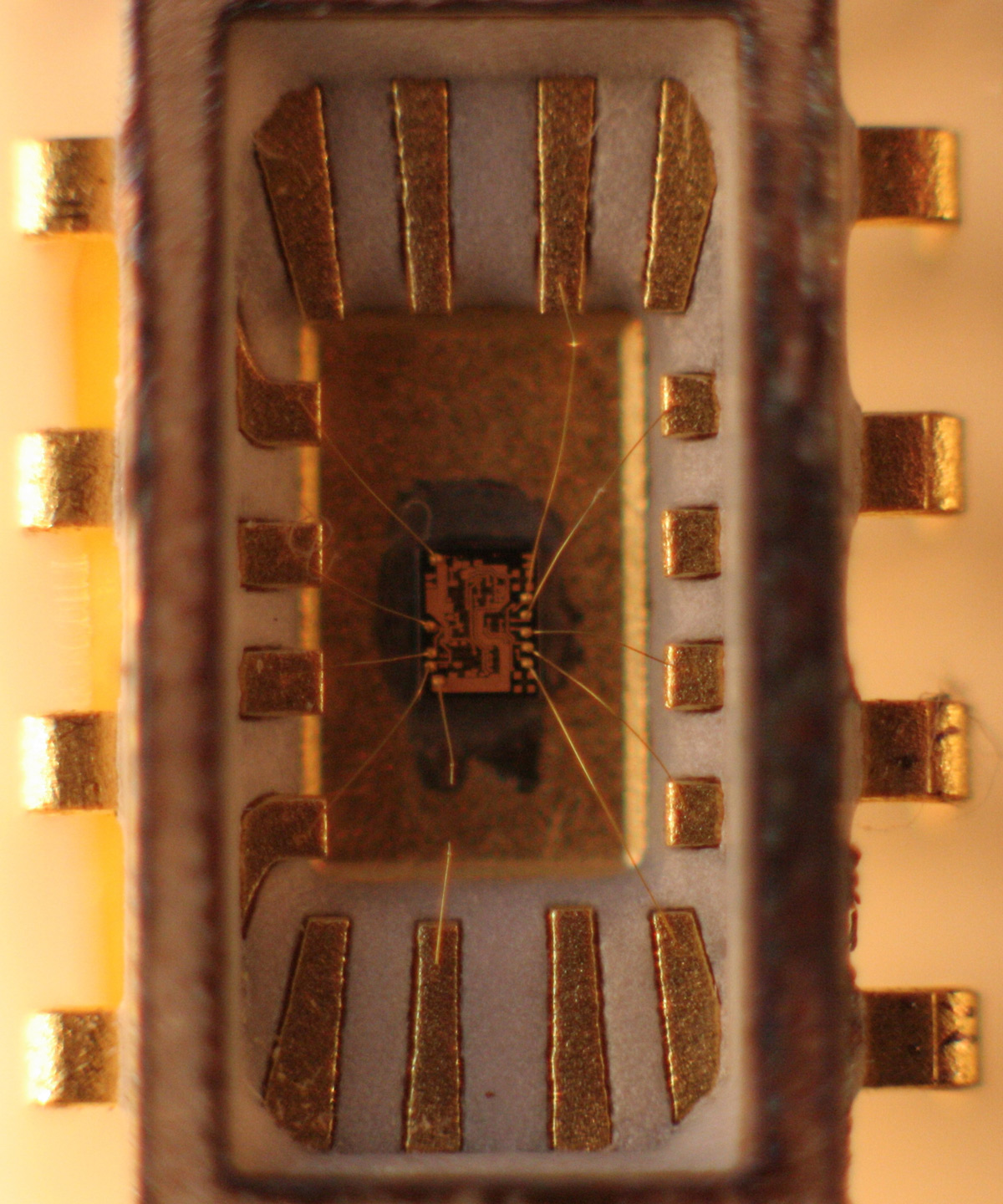
.The STOP flipflop IC (A22U21) was removed from the circuit and its top goldplated Kovar cover was removed with the aid of a propane torch. The internal gases in the chip mounting cavity expanded and popped the lid off.
Using a 10x magnifying glass it was clear that the open ground gold bond wire had a small gap in it. This gap is clearly visible in the image shown below.
|