 |
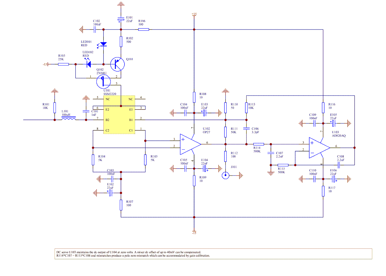
The circuit uses a low flicker noise SSM2220 pnp input stage with an OP27 output stage and an AD820 dc servo (integrator) stage. It has a gain of 60dB and a <1Hz to >300kHz 3dB frequency response. It can accommodate mixer IF port dc offsets of up to 40 millivolts. When the offset is smaller than this R113 can be increased to extend the low frequency response without increasing the capacitance of the integration capacitors (C107 and C108). For example when the offset is less than 4 mV, R113 can be increased to 100k extending the low frequency response by a factor of 10. It is suitable for use with PC sound cards and low frequency spectrum analysers for measuring phase noise. The offset frequency range is [20Hz, 20kHz] when using a sound card.
Originally designed for measuring mixer flicker phase noise at low offset frequencies it is also useful when measuring the phase noise of other components. With appropriate software a cross correlation phase noise measurement system can be assembled incorporating a PC sound card and a pair of these preamps.
The design derives from Enrico Rubiola's low noise mixer preamp design: pnp input low flicker noise 50 ohm source preamplifier
The noise and power supply rejection of the input stage current source have been improved and its cost reduced. The 0.01% low drift collector load resistors (R104 and R105) and offset trimming network are replaced with cheaper 0.1% resistors to reduce cost without significantly impacting performance as the dc servo ensures that amplifier output dc level is very small.
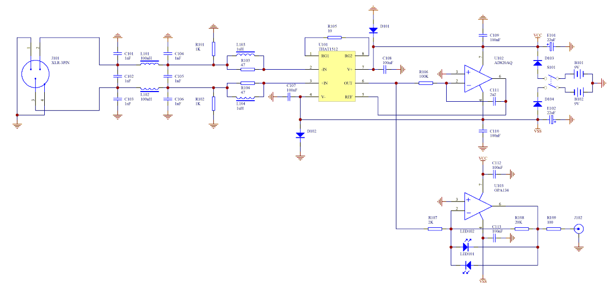 |
The above differential input mixer preamp has a gain of 80dB and is suitable for use with a PC sound card where the sound card low frequency cutoff is 10Hz or greater The LEDs ensure that the sound card input isn't overdriven. To vary the gain change the value of R105. Gains from 20dB to 80dB are possible. If R107 is increased a gain of 0dB is also feasible. For low phase noise OCXOs a gain of around 80dB or so will be required to raise the amplified OCXO phase noise above the noise floor of the sound card. For noisier sources less gain is required.
TBC...
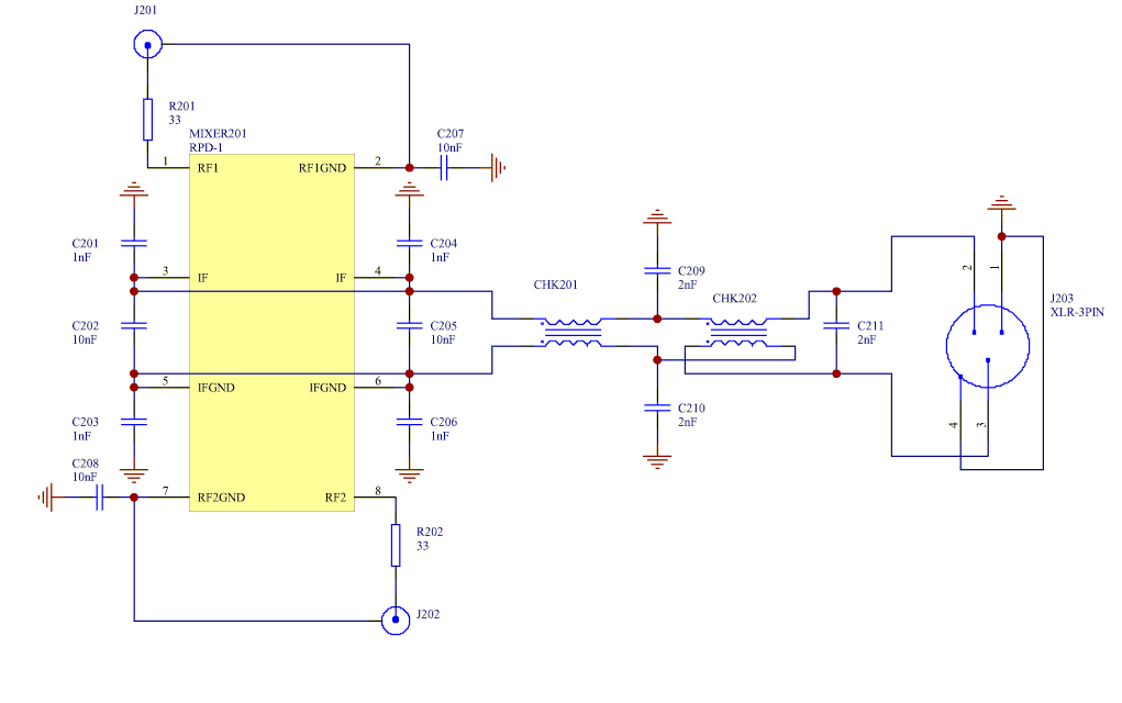 |
The above schematic illustrates how the mixer ports should be terminated for low output noise and minimum input VSWR.
TBC...
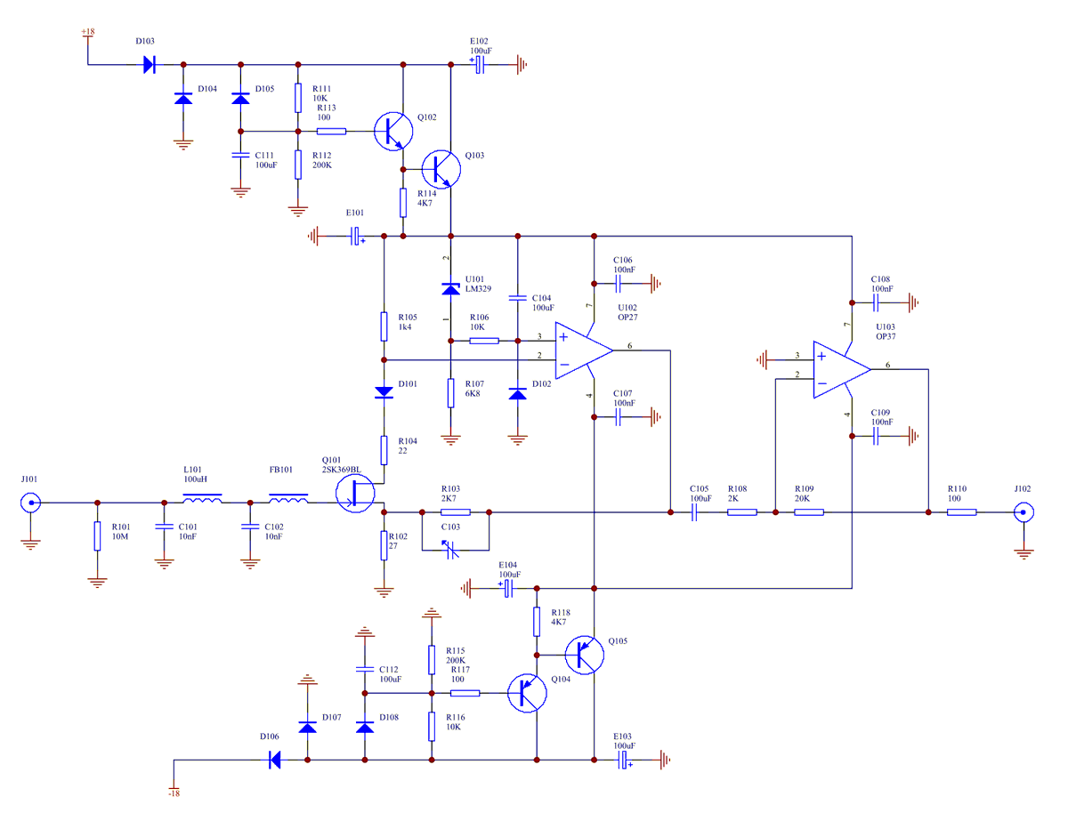 |
Sometimes when testing a delicate and expensive mixer it is desirable to avoid destroying the mixer should a preamp power supply fail (or be disconnected). The above single ended FET input preamp ensures that the current injected into the mixer should one of the preamp supplies be disconnected is at most a few nA at room temperature. The resistor network at the FET source ensures that the FET gate source junction cannot be forward biased by more than 0.15V ensuring that the gate current is very low should opamp U101's output go to -15V. Diode D101 in series with the JFET drain ensures that when the positive supply is disconnected or zero that the opamp input stage tail current doesn't flow via the drain gate junction into the mixer.
The design is derived from Wenzel's low noise mixer preamp ( Wenzel Low noise mixer preamp ) without the unity gain dc coupled option. It is optimised for the 2SK369BL JFET and has additional components to eliminate potentially large JFET gate currents on startup and when one of the power supplies fails or is disconnected.
Whilst the input flicker noise of this preamp isn't as low as the pnp input preamp its noise is quite low (<1.5nV/√Hz) for frequencies of 10Hz or more. Its noise can be reduced by averaging the outputs of several input stages (Q101+ U101) as illustrated below:
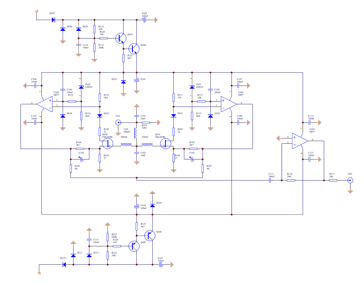 |
Averaging the output of several input stages rather than paralleling JFETS doesn't require using matched JFETs to ensure that the individual FET drain currents match to within a few percent.
TBC...