Table of Contents
FE-5680A Rubidium Frequency Standard FAQ
culled from the time-nuts mailing list, and various related web sites. Jan. 31 2012 v0.2 initial compilation by John Beale
What is a FE-5680A and why would I want one?
The FE-5680A is a Rubidium Frequency Reference made by FEI (Frequency Electronics, Inc) www.freqelec.com. As of January 2012 surplus units were available cheaply (<$50) on auction sites. The units were probably pulled from cellular base stations, which use Rb standards to keep transmitter frequencies within spec. Rb standards can provide a stable frequency to parts in 10-11 or better (over some time interval), and now a surplus 5680A may be the least expensive way to achieve that level of accuracy.
Rb frequency references are used wherever a stable frequency, time or time interval is needed. One example is narrowband radio communication links at UHF or microwave frequencies, another is simply an accurate clock independent of GPS or external signals. A Rb standard can also be corrected over the long term (weeks or months?) by GPS, in that case it becomes part of a GPSDO.
How does the FE-5680A compare with Efratom LPRO-101?
Bob Camp Thu, 02 Feb 2012 14:09:10 -0800 original post
They are pretty similar units.
They are both within about 7×10^-12 to 1.5×10^11 at one second. Both are within about 1 to 3×10^-12 at 100 seconds. Good samples of both will get much better than that out past 100 seconds. Bad samples of each, not so much. You would have to test a pretty good sized sample to really tell who pulls ahead on short term. Limited data says that the FE is *maybe* a bit better than the LPRO.
Both have a temperature coefficient in the 3×10^-10 vicinity over 0 to 70C “worst case”. Good samples of each do much better.
Both units age very little on a daily or weekly basis. You have to watch them for months / years to see real aging. Good samples of each will get down below 1×10^-11 per month. Poor samples do exist.
The LPRO has a cleaner RF output spur wise. The power output on the FE's seems to range from +3 to +10 dbm depending on which unit you look at. Power output on the LPRO is a bit better unit to unit. Neither unit is in the “rock star” category for either phase noise or spurs.
The FE runs off of an easier to find supply voltage (+15 rather than +18).
The monitor outputs and pps out on the FE are a bit weak. Not a problem if you are driving CMOS logic. The LPRO is better at driving heavier loads. FE's seem to show up without a pps output. I have not seen that issue on LPRO's.
Both units pull a major chunk of power at turn on, both get quite hot without a heat sink (or fan) at room. Neither one is suitable for higher temperature operation without some sort of thermal management.
FE's right now are in the vicinity of $40 delivered. LPRO's were in this vicinity a couple of years ago if you knew who to get them from. LPRO's are more expensive now. The FE's are going up in price.
The LPRO tunes with a voltage and a tuning pot, the FE has a cool serial interface and an eprom.
Both units warm up and lock in a similar amount of time. The LPRO lets you look at a voltage to watch the VCXO tune, the FE lets you play with (often undocumented) serial commands see what's going on.
The FE interfaces through a DB-9 connector you can get pretty easily. The LPRO uses something a bit less conventional, but still available.
Schematic and parts list on both units is a bit of a mystery. There is a bit more on the LPRO simply because people have been reverse engineering them longer.
Bottom line, they are very similar devices. The only big deal is the serial interface on the FE vs the tuning on the LPRO. You could easily get a better (or worse) unit buying either part.
Measured Frequency stability
from Mark Spencer Fri, Feb 03 2012
Performance very first impressions: Yesterday I took delivery of two 5680's. In case anyone is interested, I'm seeing adev numbers in the 2 to 2.5 E-12 range from 80 thru 200 seconds. The unit under test has been running for approx one hour and I let it warm up for 30 minutes before collecting data. The reference is an fts1050 and the data is being collected with an hp 5370B. Not to bad for $40.00 IMHO.
from Bert Kehren, Jan 17 2012
After eight weeks of monitoring to 1 E-12, I still see no aging. Waiting for a change so I can do other tests. One thing I clearly see is a 4 Hz filter response changing the output by +- 3 E-11. It may be more, will have to find a way to check it more accurately, because of limited response time.
- Performance plots from KE5FX (showing Allan Deviation for 5680, LPRO, PRS10, HP 5065A)
- Performance plots from N8UR (showing Allan Deviation for 5680, FRS, LPRO)
Electronic Frequency Control (EFC)
from Ed Palmer, Mon, Dec 31, 2012
A few years ago I got one of the programmable FE5680 units. It included the same small, square board that I can see in [Fabio's] FE-5682A pictures (http://www.flickr.com/photos/14336723@N08/sets/72157632394339366/). Only 3 wires: red, black, and orange. My unit didn't have any EFC control. On a hunch, I checked the orange wire and found that it was the EFC lead. By disconnecting it and injecting a DC voltage into the main board, I could adjust the frequency of the oscillator over a range of about +- 1.5 e-9 (i.e. 1.5 ns on the 1 PPS output) for a 0 - 5 volt input.
Useful Links
Time Nuts mailing list archives: febo.com and also at mail-archive.com
Frequency Electronics official FE-5680A product page
FE-5680A Technical Manuals Earlier Manual Manual for 5680-0211 version
Useful VK3UM FE-5680A page Notes, links, and control software
Extensive info on packaging for ham radio use on KA7OEI page
Notes on four different units, two with SMA connectors on VK2XV page
FE-5680A variant with 1 Hz-20 MHz synthesizer (usually > US$100 on auction sites) DD1US page
Some signals marked in this photo
Misc FE-5680A photos
Atomic Nixie Clock project, using 5680A as timebase on AMUG.org page
Datum/LPRO-101 Rb reference, a bit different but has general theory of operation, and usage details LPRO manual
SRS PRS10 Rb reference, a different unit but has a good theory of operation section PRS10 manual
Symmetricom XPRO, a similar Rb unit: datasheet manual
More detailed explanation of physics behind Rb frequency references OpenHPSDR.org paper
How to repair a Rb discharge lamp (heat gun restores precipitated Rb to usable form) N4IQT FRS Lamp Repair
Video tour of FE-5680A Interior, EEVblog #236 Youtube video
Useful collection of general-purpose, high resolution frequency and timing links KE5FX Stability page
NOTE: there are MANY different varieties of “FE-5680A” with many options so any specific feature, output, or repair procedure may not apply to your unit. See for example, the options listed in the FE-5680 Tech Manual.
Parameter Specifications
from FE-5680 Tech Manual Table 3, Sheet 9 (PDF page 10/19):
- Frequency 10 MHz
- Type Sinusoidal
- Amplitude (minimum) 0.5 Vrms into 50O(+7dBm)
- Adjustment Resolution <1 x 10-12 over range of 3.8 x 10⁻⁵
- C-field potentiometer Resolution 1 x 10-11 over range of 3 x 10⁻⁹
- Drift: 2 x 10⁻⁹ per year, 2 x 10-11 per day
- Short Term Stability: 1 sec … 100 sec 1.4 x 10⁻¹¹ t
- Retrace 5 x 10-11
- Phase Noise (fo=10 MHz) @10 Hz: -100 dBc, @100 Hz: -125 dBc, @ 1000 Hz: -145 dBc
- Input Voltage Sensitivity 2 x 10-11 (15V to 16V)
- Frequency vs.Temperature (-5C to +50C) ±3 x 10⁻¹⁰
- Spurious Outputs -60 dBc
- Harmonics -30 dBc
- Loop Lock Indication: > 3Vdc=Unlocked, < 1Vdc=Locked
- Input Power (@25 C) 11 watts steady state, 27 watts peak
- DC Input Voltage/Current
- 15V to 18V @ 1.8A peak and 0.7A steady-state
- …(except Opt 25: +22V to +32V @ 1.25 peak, 0.5A steady-state)
- Ripple +15V: < 0.1Vrms
- Warm-up Time < 5 minutes to lock @ 25C
- Size: 25 x 88 x 125 mm, .98 x 3.47 x 4.92 inches
- Weight 434 grams, 15.3 oz.
Connector Pinout
- pin 1: +15V input (1.7A max when cold starting, 0.6A typ steady state)
- pin 2: GND (15V return)
- pin 3: LOCK (low=locked, high=unlocked. Weak, can drive < 1 mA)
- pin 4: +5V input (80mA typ.)
- pin 5: GND (signal)
- pin 6: 1pps (about 1us positive pulse per second, only when locked, and if you don't load pin 3 by driving a LED)
- pin 7: 10MHz sinewave (~1Vpp on 50 ohm)
- pin 8: RS-232 RX (receive commands into unit)
- pin 9: RS-232 TX (unit sends responses to pc)
from Jose Camera Apr 20 2011 pinout post
Why doesn't the C-field adjustment trimpot through the hole in the side do anything?
Some versions of the 5680A (most/all available on auction sites as of Jan. 2012) have this circuit disconnected. So, it doesn't do anything. However, you can program the frequency offset via RS-232 serial commands though, see “control software” link above, or add your own pot or Vin connection; see below.
Adding an Analog Adjustment Pot
by Bill Riches, Thu, 22 Dec 2011 14:01:18 -0800
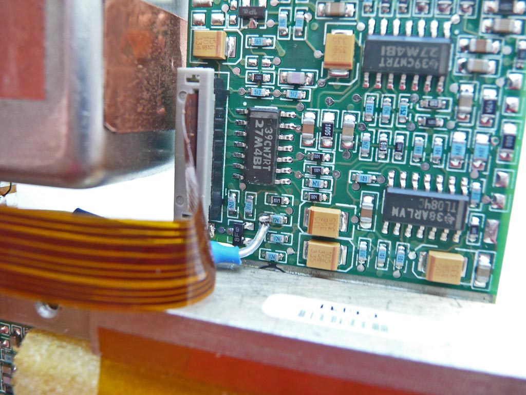
As has been mentioned by Pete and others the majority of the inexpensive 5680 units can only be adjusted for frequency by inputting rs232 info. I am experimenting with a simple mod to add a fx adjust pot to my unit. I removed the unconnected “dummy” pot and glued a miniature 100 k pot upside down in the area where the original pot was. Its connections are on the top of the pot. Cold side of pot went to ground, hot side of pot went to output of 8 volt regulator through 1 k resistor. Wiper goes through a 100k resistor to pin 5 of the chip next to the ribbon connector. (To find pin 5 have unit positioned with db9 connector at upper left, ic area will be in lower right. Pins 1 through 7 are between the chip and the ribbon connector - pin 1 is at the extreme right next to the marking on the chip - count left to pin 5! I got my 8 volts from the 8 volt regulator that is the first xsistor of the two that are mounted on the vertical heatsink. The third pin is 8 volts output. Pins are counting down from db 9 connector area.
The chip is marked “27M4BI”, located on the right in the photo, next to the flex cable. There is a white dot silkscreen on the PCB near pin 1. It is a TLC27M4B quad opamp; pin 5 is a noninverting input.
Three hours after doing this mod my unit is about 5×10-12 high. The voltage on pin 5 is 3.52 volts. I have my thunderbolt 10 mhz output triggering my 465, the 10mhz from 5680 going to vertical input, time base set to .1 usec and the x10 mult on giving me .01 usec per div. With a stopwatch I time the time it takes for the trace to move one division. I divide the seconds measured and divide that into 1 to the minus 8th and get the offset. in this case 1 to the minus 8th divided by 195 seconds gives me about 5 parts in 10 to the 11th. The trace is moving to the left which means the osc is high.
- from Arthur Dent, Sun Jan 15 18:31:39 UTC 2012 original post
I didn't solder the resistor directly to pin 5 of the IC. I found that pin 5 was connected to a nearby SMD capacitor that was a little easier to solder to. Here is a photo of the correct location if you want to try bringing the EFC out for analog control.
…I'd go with Bill Riches' suggestion to have the 100K in series with the EFC line. I connected the lead from the 100K to a pin on the DB-9 connector that was freed up when I put the 5V regulator inside so I could run off a single supply.

What is the range of frequency adjustment via RS-232 commands?
The offset setting is a 32 bit signed integer. In one version of the FE5680A having a 60 MHz VCXO, each individual step is 6.80789e-6 Hz (or 6.807e-13 relative to 10 MHz. (Note: the manual claims an older (?) version with a 50.255055 MHz VCXO had a finer resolution step of 1.78E-14). The adjustable offset is intended as a fine trim control, and the unit may not even lock at the extreme settings. The frequency output has also been reported to become less stable as it is set farther away from 10.000000 MHz. The DDS chip used is the Analog Devices AD9832.
FREQUENCY ADJUSTMENT 2-3
Introduction 2-3.1 The FE-5680A output frequency can be adjusted digitally over the RS-232 interface (pins 8 and 9). This feature is available as option 2, and is not available on units purchased without this option. The frequency can be adjusted with a resolution of 6.80789e-6 Hz. For an FE-5680A device with an output frequency of 10 MHz, this corresponds to a relative frequency setting resolution of 6.807e-13.
In order to perform adjustments to the FE-5680A over the serial interface, commands conforming to the protocol described in this section must be sent. The signal levels must conform to the RS-232C requirements. Commands are sent to the FE-5680A using the TX line (pin 9), and response from the FE-5680A are received on the RX line (pin 8). The TX and RX signals are referenced to system ground, pin 5. […]
from FE-5680 Tech Manual Sheet 16 (p. 17/19) corrected for 60 MHz variant
What if my 5680A output does not lock up after several minutes?
John Beale, Dec. 2 2011
Within 5 minutes after powering up (apply +15V on DB9 pin 1 and +5V on pin 4) the unit should indicate lock (pin 3 voltage drops low). If it does not, the internal VCXO frequency may have shifted enough so the loop does not pass through 10 MHz and achieve lock. If you have a frequency counter, look at the 10 MHz output signal before lock to see if it sweeps through 10 MHz or not. One of my units would only reach 9.99998 MHz as I received it, but I fixed it with C217 adjustment, as below.
Open up the top cover by removing screws (some hidden underneath labels on top) Gently move aside the insulating foam blocks (they are fragile). Rotate trimmer cap C217 slightly with a screwdriver. Power up again and wait 5 minutes to see if it locks. Repeat as needed. See also these illustrations:
- Photo of PCB with C217 trimmer (also crystal with PTC soldered on top)
- Plot of startup frequency sweep (works; center frequency still a bit low)
Can I get a square wave 10 MHz output instead of a sine wave?
Yes, by removing the bottom plate, lifting one end of a 15 ohm resistor on the Xilinx XC9572XL CPLD pin 49 (10 MHz square wave output), and installing a cable to bring out the signal. See J.Beale's modification shown here:
The CPLD is a frequency divider, which takes as input a 60 MHz 2.8 Vpp sine wave input from the VCXO, which goes into CPLD pin 64. Pin 22 has a 30 MHz square wave. Some FE5680A units reportedly have a 1 us wide 1 PPS (1 pulse per second) signal on the DB-9 pin 6, but only when locked.
The 1PPS signal comes from CPLD pin 45 and it is buffered at U503 (74HCT240), and it is also gated there by the Lock signal. The lock signal is not buffered, so if it is externally overloaded (eg. by directly driving a LED) the gate doesn't open and the 1 PPS signal is lost.
How can I get a 1 PPS output?
A 1 microsecond wide, logic level 1 PPS signal appears on the DB-9 pin 6 whenever the unit is locked (hard to see on an analog scope, should be easy on a digital scope). The PPS signal does not appear until the unit is locked (pin 3 goes low). The current sink capability of pin 3 is weak, and if it is driving an LED + 1K resistor from +5V, that will leave pin 3 at 2.3V when locked, not enough to enable the 1 PPS signal. Advice: buffer the pin 3 lock signal before driving an indicator light. All being well, pin 1 of the 74ACT240 will drop low in step with the lock condition and the PPS signal will appear at the DB9.
Alternatively, it is easy to get a 1 pps signal from the 10 MHz output with a single picDIV chip (possibly with a 0.1uF cap and two 10k resistors to bias the sine wave to 1/2 the PIC power supply voltage). picDIV parts (based on PIC12F675 cpu) from Tom Van Baak take a 10 MHz clock input and generate a 1 PPS output. See also: http://www.leapsecond.com/pic/picdiv.htm
Thanks to Bob Grant for describing the pin 3 LED ⇒ pin 6 PPS problem.
What is the typical drift with temperature (tempco)?
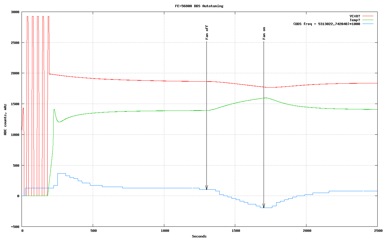
The official spec says +/- 3×10⁻¹⁰ from -5C to +50C (FE-5680 Tech Manual, Table 3). One of my units shows -7×10-12 frequency change per degree C increase in case temperature (measured at case temp. of 45C and 55 C). For this reason it is beneficial to stabilize the temperature, for example with a thermostatically controlled fan blowing on the unit's heasink. Photo of unit with attached heatsink and fan.
The 5680A actually measures its internal temperature and applies a compensating offset to the internal DDS, as you can see in this plot from N5TNL. Each Rb bulb has a unique temperature coefficient, and it is possible that it might change with time, so the correction on some units might not be as good as others.
Input Voltage Requirements (spec is 15 - 18 volts DC, and 5V DC)
from Pete Bell, Jan. 18 2012
One of the regulators (the one that runs the lamp and lamp heater) is running at 13.8V and has a 500mV dropout voltage, so there is very little (~ 700mV) headroom. The one that runs the cell heater is about a volt lower and the one that runs the analog circuits is set to 8.8V, so has plenty of headroom.
I suspect the lamp regulator is mostly there to reduce the start-up current, though - the FE-5650 has a very similar lamp circuit with no regulator and the only significant difference seems to be that the current pulled when the unit is cold is higher.
from Ian, Jan. 19 2012
With 15.5V DC input power it locks in about 3min. I backed off the supply to 10.8V and the lock time (from cold) is 8min.
from Steve, Feb. 21 2012
A few weeks ago I performed a thermal test while noting the power use of the FE-5680A. My intentions were the least amount of power use possible. I was able to get the total power consumption of the frequency standard below 6 watts and maintain lock. To do this I housed the standard in a make shift thermal insulator using shipping bubble wrap, aluminum foil (as a radiation shield), and a terry clothe. – items I was able to find while at work.
The temperature leveled off around 67c and likewise the wattage < 6 watt. The conditions were simply to start the standard with normal voltage / current. Then when lock was achieved I set the power supply to voltage control mode and slowly started to drop the voltage.I took 45 mins of slowly dropping the voltage until i finally reached the minimal wattage. Taking 100mv or so at a time, noting the current you can actually see the heating characteristic of the standard. Wattage will will first drop as the voltage is dropped, it will then increase due to increase of current presumably in the heating circuitry, and then it will drop again and reach an equilibrium. After the equilibrium is reached, I would again drop the voltage. The process continued until I lost lock, which I then increase the voltage and again waited for equilibrium. Then after lock I began to drop voltage again.
Below are the lowest V*A which I was able to demonstrate a maintained lock.
- voltage: 9.96v
- current: 543ma
It is necessary to use a heatsink?
It is a good idea to limit the case temperature to 60 C, or lower to extend unit life. For example, the user manual for a similar Rb unit, the Symmetricom XPRO estimates that the lifetime doubles when baseplate temperature is reduced from 60 C to 40 C (MTBF: 243k hours ⇒ 591k hours).
Also, the largest source of frequency drift is likely to be temperature, so for the best performance the temperature can be stabilized with a thermostatically-controlled fan directed at the unit's heasink. Since the Rb chamber does have an internal thermostat control, the unit will draw proportionally more power as the baseplate is cooled.
Is a Rb standard affected by magnetic fields?
Yes.
- “The magnetic field dependence of the resonance frequency of the rubidium microwave transition, for example, is given by FRb = 6 834 682 613. + 574 H2 where F is in hertz, and the magnetic field H is in oersted.” from nist.gov
For reference: In a vacuum (permittivity = 1) if magnetizing field is 1 oersted, then magnetic field strength is 1 gauss. The earth's magnetic field is roughly 0.5 gauss, so it would contribute 143 Hz to the 6.835 GHz Rb frequency (a relative offset of 2.1E-8) if the device was not magnetically shielded. As well, any variation in this field would cause a corresponding variation in frequency. This is why all Rb standards are magnetically shielded, for example with one or more layers of high-permeability mu-metal.
The LPRO-101 manual (another Rb unit) mentions sensitivity to DC and AC magnetic fields, but “under 2 gauss should not result in measureable permanent frequency offsets for LPRO.” The FE-5680A case is made of a magnetic shielding metal, so it should not be removed (for better heatsinking, etc.) unless the heatsink itself is also magnetically shielded, or the unit is installed away from all stray fields (which is very difficult in most locations, since any electrical current generates a magnetic field). In particular, power supplies and cooling fans may generate strong nearby magnetic fields.
Can you tap into the GHz output from the rubidium?
from Tom Van Baak Mon, 30 Jan 2012 21:25:53 -0800
Most rubidium frequency standards (and cesium for that matter) do not actually output that frequency. I know in the popular press they talk about the “precise vibrations of the cesium atom” or the “precise frequency that they emit” but that's a metaphor and not how they actually work. The atoms don't vibrate, they don't emit a GHz frequency, and you don't count 9,192,631,770 of them to make one second.
What typically happens is that electronics synthesizes an RF (microwave) signal and continuously sweeps across a narrow range of frequencies; the element (Rb or Cs or H) will respond more or less depending on how correct the probe frequency is. A servo then tries to keep the probe frequency centered on the peak. These are all called “passive” standards.
The rare exception is the “active” hydrogen maser; where there really is a live signal (1420+ MHz) coming out of the apparatus.
You may find these two papers helpful:
Mechanical
- Size: 25 x 88 x 125 mm, .98 x 3.47 x 4.92 inches
- Weight: 434 grams, 15.3 oz.
- Some surplus units, which come screwed onto a PCB, are attached with 1/16“ hex screws
Electronic Parts
The main digital electronic parts are:
- Maxim DS80C323END (8051, 44TQFP, -40/+85C, 18 MHz, 4 8-bit ports, 64K/64K ROM/RAM ) datasheet
- STMicro PSD813F1V-20UI (1Mbit flash, 256Kbit EEPROM, 16Kbit SRAM, 3k PLD gates, ISP) datasheet
- Xilinx XC9572XL VQ64BN (64-pin CPLD, 178 MHz, 72 macrocells) datasheet
- Analog Devices AD9832BRU (25 MHz Direct Digital Synthesizer, on-chip 10-bit DAC)datasheet
Other ICs on digital side of PCB:
- Maxim MAX708 CPU supervisor
- Maxim DS1832 CPU watchdog, brownout detect
- Maxim MAX882 3.3V LDO (5V input)
- Maxim MAX1246 4 channel 12-bit ADC, 4-wire SPI interface
- Maxim MAX3232 RS-232 transceiver
- Fairchild 74ACT240 octal buffer / line driver, tristate outputs
Analog side of PCB:
- NatSemi LM2941 1A LDO regulator (3x)
- Fairchild IRFU220 4.6A 200V MOSFET (on Rb lamp, 2x)
- TI TLC27M4B quad CMOS opamp (4x)
- TI TL084C quad JFET opamp
- Maxim MAX4117 400 MHz current-feedback dual op amp (2x)
- Maxim MAX392 precision quad SPST analog switch
Scans & X-Rays of PCB
- annotated images of PCB 1(.JPG/1.4MB) editable format(.PSD/39MB)
- High resolution BOTTOM view with ICs(.JPG/10MB) without ICs(.JPG/8MB)
- High resolution TOP view with ICs(.JPG/10MB) without ICs(.JPG/10MB)
- set of PCB X-Rays revealing internal layer tracks from Rich in this 26-Mar-2012 posting
- modified X-Ray images based on Rich's X-Rays, done by Jose Camara in this 28-Mar-2012 post
Circuit Operation
Block Diagram of version 5680-0211

Digital Logic connections
- partial digital schematics v0.3 (updated on 2012-11-08) from Elio Corbolante
- FE-5680A Firmware dump (dumped on 2012-11-08) from Elio Corbolante
- ST Micro datasheet shows CPU-PLD connection schematic (image below). See also this post from Elio Corbolante.

Frequency Synthesizer Chain
A 60 MHz sine from the VCXO enters CPLD pin 64 and it generates 3.3V square wave outputs at 30 MHz (pin 22), 20 MHz (pin 1), and 10 MHz (pin 49). The 20 MHz output goes to the clock input of the AD9832 DDS chip, which generates a 5.313 MHz sinewave output (nominal, when the RS-232 offset is set to 0). The frequency resolution of the DDS itself is (Fclock)/2^32 and since Fclock=20 MHz, the 5.313 MHz output is tuned in steps of 4.657E-3 Hz (see also DDS notes below). The FE-5680A frequency chain is apparently similar to the Efratom FRS model. See Efratom FRS Manual page 3-8 (and notes on p.19) for a summary of operation of the frequency synthesizer ( 114 * 60 Mhz - 5.313 Mhz → 6.835 Ghz). 6.835 GHz is the Rb hyperfine transition used to reference the oscillator. This is also summarized in Efratom LPRO 101 Repair Guide.
DDS SPI Bus
from Javier, EA1CRB Jan 30 2012
I've hang a logic analyzer to the DDS SPI bus, and an SPI message appears inmediately after updating the offset through the serial port. I've found that the DDS is programmed in two frequencies, separated 1400Hz near exactly, for each serial port offset setting, and that one bit increment in the serial port offset setting is translated to a one-bit increment for both DDS frequencies. The DDS frequencies are alternated at 416.6666666Hz rate through FSELECT pin, at an invariable 50% duty cycle, presumably to perform synchronous detection in the same way as explained in the FRS-C manual.
For example, the following data has been gathered:
Serial offset 00 00 00 00DDS A word: 44 02 62 F6 = 1141007094 = 5 313 228.32219 HzDDS B word: 43 FD CC 8E = 1140706446 = 5 311 828.32085 Hz
Serial offset 00 00 00 01DDS A word: 44 02 62 F7 = 1141007095 = 5 313 228.32685 HzDDS B word: 43 FD CC 8F = 1140706447 = 5 311 828.32550 Hz
Serial offset 00 00 00 02DDS A word: 44 02 62 F8 = 1141007096 = 5 313 228.33151 HzDDS B word: 43 FD CC 90 = 1140706448 = 5 311 828.33016 Hz
I've seen that these values seems to vary slightly from time to time in the less significative digits, I've been then change in the order of 2-3 units from one data take to a different one minutes later. I've checked that the unit updates each several seconds the DDS control words, and I've seen changes in the lower significant bits at minutes intervals, although most of the times, same previous words are sent. I suspect this is some form of unit self-compensation, perhaps to temperature changes.
Last, I've sent an offset of 1468879 units, that shoudl correspond to a 10Hz frequency change assuming a trimming resolution of 6.90789e-6Hz, and after a temporary unit unlock, it has locked exactly at 10 000 010.000 Hz. So I can conclude that these units are not fully compliant with the manual we are handling, and that the trimming resolution is 6.80789e-6Hz
Undocumented RS-232 commands
from Scott Newell N5TNL, Jan 18 2012
I get a response from the unit to several undocumented serial port commands. In particular, the replies from 22, 57, 59, and 5A seem to vary each time I read the unit. Not all the commands respond each time; there's certainly a bug or two lurking. (I'm probably getting the poor unit's serial input all confused and out of sync.) Anyway, commands 57 and 59 appear to send back a lot of data: 0x56 bytes! I'm not yet validating the data length or checksum of the FE-5680 reply.
Later Note
Command 5A may be reading an internal 4-channel, 12 bit ADC, possibly connected as below. See also http://n5tnl.com/time/fe-5680a/
- Ch.1: trim pot
- Ch.2: supply voltage
- Ch.3: temperature
- Ch.4: VCXO control voltage
These commands must be put into a standard 4 byte format. For example, the 0x5a command is issued as 0x5a 0x04 0x00 0x5e. The last byte is the checksum (XOR of 3 preceding bytes). The data format of the response is shown in the table below.
| Message Section | Offset | Description |
|---|---|---|
| Command Header | 0 | Command ID |
| 1 | Low-byte of message length | |
| 2 | High byte of message length | |
| 3 | Checksum of bytes 0, 1, and 2 | |
| Data | 4 | Data Byte 0 |
| 5 | Data Byte 1 | |
| . | ||
| . | ||
| . | ||
| n | Data Byte n | |
| n+1 | Checksum of byte 4 to n |
The command and response format is described on Sheet 15 in the FE-5680 Tech Manual.
Example of commands and response data (hex values)
| Command | # Bytes | Response Data | Data |
|---|---|---|---|
| 22 | 0D | 22 0D 00 2F 20 5B 29 00 A1 C8 4A 1D 6C | DDS Value |
| 29 | 09 | 29 09 00 20 FF 00 00 00 FF | |
| 2B | 09 | 2B 09 00 22 20 5B 29 00 52 | |
| 2D | 09 | 2D 09 00 24 20 5B 29 00 52 | |
| 47 | 08 | 47 08 00 4F 20 5B 29 52 | |
| 53 | 07 | 53 07 00 54 79 00 79 | |
| 57 | 56 | 57 56 00 01 20 20 5B 29 00 A1 48 4E 1D C0 00 D6 | |
| 72 85 6A DB 25 80 14 8A BD 2E 5E 86 CB BA E5 CA | |||
| F5 2D 0F 4F 7F D3 D1 37 2B 2C 90 54 45 68 9A AC | |||
| AA 4B 50 33 CF 9B 2B FD BD E6 AD 6D 6B BA FF FA | |||
| 17 03 62 F4 E8 79 00 83 23 C1 17 69 37 18 8E E9 | |||
| 13 A3 FB 1F 1B F8 | |||
| 59 | 56 | 59 56 00 0F 20 20 5B 29 00 A1 C8 4A 1D 40 00 D6 | |
| 72 95 6A DB 25 80 54 8A BD 3C 5E 86 C9 BA E5 CA | |||
| F5 2D 0D 4F 7F D3 D5 37 2B 2C 90 54 45 68 BA BC | |||
| EA 4B 50 33 CF 9B 29 FD BD E6 AD 6C 6B BE FF FA | |||
| 15 02 62 F4 E8 D8 57 83 23 C1 17 68 37 18 86 E9 | |||
| 13 AB FB 5F 1B 79 | |||
| 5A | 0D | 5A 0D 00 57 00 00 40 08 9E 07 00 00 D1 | 4 ch. ADC |
| 61 | 09 | 61 09 00 68 20 5B 29 00 52 | Serial Number |
| 65 | 07 | 65 07 00 62 20 20 20 | |
| 67 | 08 | 67 08 00 6F 01 F4 B8 4D | |
| F0 | 0E | F0 0E 00 FE 33 2E 34 00 00 00 00 00 00 29 |
The actual data payloads are shown in bold. The other bytes are command string, and final checksum